Pressure control in the electrohydraulic power unit
Control using electrohydraulic proportional or servo valves is usually achieved by using a power unit that maintains a constant inlet pressure to the control valve. Such design strategy offers several advantages and raises several issues:
- With a high-pressure supply, hydraulic power is available immediately when a signal is given to open the valve. That is, there is no need to wait for pump pressure to build before flow occurs and the load moves.
- Conventional servo and proportional valves can be used because nearly all have a closed-center center spool position.
- Because the valves are closed center, a pressure regulating supply is must be used. Pressure-compensated pumps are a frequent choice for regulating pressure.
- That greatest final accuracy is achieved by regulating the valve supply pressure to the lowest practical tolerance. That is, supply pressure is kept constant, regardless of the variation in flow demand by the load.
A pressure-compensated pump may be able to supply hydraulic power at a relatively constant pressure in the face of flow demand changes by that can suddenly increase from zero to maximum, and vice-versa. Then again, it may not. Depending on the circumstances, an accumulator my be used to supplement pump flow during brief periods of peak flow demands. But often, the pressure-compensated pump by itself will suffice.
This begs the question: Do any simple rules of thumb exist to help circuit designers determine the need for an accumulator? The short answer is yes, and my immediate aim, here, is to explain how it works. I'll introduce a sample system to explain the process.
A sample scenario
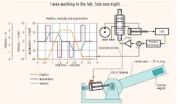
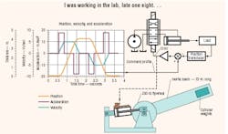
The sample system is typical of a position feedback servo system that follows a command profile. It is shown below in Figure 1. The graph on the left shows the acceleration, velocity, and distance motion command profiles. A simplified circuit is on the right, and an illustration of the physical installation is shown at the bottom. The cylinder has a bore of 2 in. and a rod diameter of 1 3 /8 in., to accommodate gun-drilling for a magnetostrictive position transducer. Driving the system is a piston pump with a conventional pressure compensation mechanism.
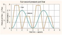
Fig. 2. Results from test show relationship between flow and displacement.
As with all electrohydraulic position servo mechanisms, the cylinder is fitted with a position transducer that feeds a signal back to a summing junction in the servo amplifier. The command signal into the summing junction is the position profile from the graph of Figure 1. This signal, of course, would be supplied by a control computer or motion control card from a PLC.
As the command profile voltage rises, the error between it and the feedback is amplified in the servo amplifier. The amplifier then opens the valve, which directs flow to the cylinder to cause its motion to try to keep up with the command. The result is a regular, cyclic cylinder motion that continues as long as the command profile repeats.
This system was chosen because it is a research tool that already exists in my IDAS Engineering research lab. The accompanying performance graphs are real data, not theoretical. They could be data collected from any industrial machine that undergoes regular, reasonably uniform, cyclic motion. The laboratory simply offers the opportunity to monitor and record all the key performance variables.
Mapping out tests
Two tests will be conducted on the sample system. The first will use only a pressure-compensated pump with no accumulator. It will be controlled by a command profile that requires 4 seconds to complete one cycle. Two complete command motion cycles are shown on the graphs contained in Figure 2. This display strategy improves the graphical data presentation regarding the pressure changes. The command distance profile and the resulting pressure-port flow to the valve are shown in Figure 2. Note that the command profile in Figure 2 differs slightly from the one of Figure 1. This occurs because the command used in this series of tests has slightly shorter dwell times at the ends of both extension and retraction. This difference has no effect on the observations or conclusions we are about reach, it is merely noted for the record.
The second test will also be conducted without an supplementary accumulator. However, the motion command profile will be speeded up so its cycle will be completed in only 1 second. It has the same general shape as in Figure 2, but everything will be commanded to happen four times faster. This test will be discussed next month.
Two different flow peaks exist during each cylinder cycle in Figure 2. The higher one corresponds to the cylinder undergoing extension. The lower peak corresponds to the cylinder during retraction. The difference, of course, is caused by the area differences between the rod-and cap-end sides of the cylinder. The volume of fluid consumed by the moving cylinder is simply the area under the flow graph.
Now let's review the motion and flow profiles in Figure 2. The motion has a short dwell, at the end of which a uniform acceleration occurs up to a speed that causes an extension flow of about 14 in. 3 /sec. The acceleration time is about 0.6 sec. Next, a constant-speed period lasts about 0.6 sec at the 14 in. 3 /sec flow mark, then deceleration to zero occurs in another 0.6 sec. Flow returns to zero again at 1.9 sec.
A dwell of about 0.2 sec occurs at extension, then retraction starts along a motion profile that is identical in time increments to that of extension. However, the cylinder area difference (a ratio of 1.896:1) results in a peak flow of about 7.5 in. 3 /sec. Meanwhile, the cylinder motion, which is almost sinusoidal, results in a maximum extension to about 5.7 in., and then retraction to about 0.3 in.
The flow profile must be supplied by the pressure-compensated pump. If pressure at the pump outlet is to remain constant in the face of the flow variations, then pump displacement must undergo substantial changes. No compensator can perfectly adjust the pump displacement, so some pressure variation must always accompany a flow variation. The aim is to keep the pressure fluctuations within tolerable limits. An intolerable limit, obviously occurs, when the pressure variations are so extreme that the cylinder does not follow the command profile within acceptable limits.
Jack L. Johnson, P. E., is president of IDAS engineering, Inc., East Troy, Wis. For information on his book, Designer's Handbook for Electrohydraulic Servo and Proportional Systems, call (262) 642-7021 or e-mail [email protected].


