Assess Health of a Hydraulic System Using a Handheld Heat Detection Instrument
Measuring the temperature of various pipes, tubing, or components, lets you detect the presence of internal leakage. This is because an increase in surface temperature often is directly related to power loss. The following discussion describes a proposed method of determining internal and external leakage rates by measuring the surface temperature of components.
Exploring Examples
Valve stands in steel mills may be mounted 100 ft or more from the cylinders. In selecting the proper diameter of pipe, hose, or tubing for a projected flow rate, a velocity of 10 ft/sec is normally used. This low velocity keeps pressure drop reasonable for piping runs, including pressure drop from interconnecting fittings.
In the following examples, assume a 6-in. bore hydraulic cylinder holds a load in place with a system pressure of 2,250 psi. In the normal condition, pressure is applied to the cap end of the cylinder to hold the load. No flow should occur.
Depending on the piping ID, length of the lines, and the time between cylinder strokes, the cylinder cap- and rod-end piping should reach a temperature of near ambient. In many cases, the run of the tubing from the directional control valve to the cylinder contains a greater volume of fluid than the volume used to fully stroke the cylinder. In this case, if no internal leakage occurs, the temperature of the fluid in the cylinder can increase only if the valve shifts to extend or retract the piston rod.
If, however, the cylinder extends 12 in. in 2 sec, the cap-end flow rate required would be 44 gpm. If the cylinder has a 4-in. rod, the flow required for the same return speed would be 24 gpm. If a schedule 80 1¼-in. pipe is used, the maximum velocity would be about 11 ft/sec.
It is common practice to plumb both cylinder lines with the same size of pipe or tubing. Doing so would produce a rod-end flow velocity of 6.12 ft/sec. The actual volumetric exchange of fluid would be 339 in.3 on the cylinder cap end and 188 in.3 on the rod end. Because the 1¼-in. piping has an internal bore of 1.278 in., every foot of piping contains 15.39 in.3 of fluid. This means that increasing the temperature of the fluid in the cylinder would require a pipe length of less than 22 ft on the cap end and 12 ft on the rod end.
Heat generation and propagation
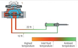
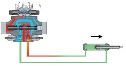
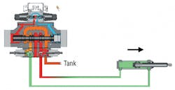
The main method of introducing heat to components and piping is to use power loss in reference to flow rate as a heat transfer device. If a 50-ft piping distance is used for the preceding example, and the valve is shifted once every minute, then the temperature gradient relative to flow may appear as shown in Figure 1.
At a certain distance from the directional valve, the pipe or tube is heated by stroking the cylinder then cooled during the reverse cylinder stroke. The amount of heat transferred through both tubes is directly related to ambient temperature, tube diameter, and the internal temperature of the fluid (at the specific distance from the directional valve). The amount of heat loss through a non-insulated tube can be approximated from the following:
Lheat= A × K × ∆T,
where Lheat = heat loss — btu/(hr × ft)
A = pipe or tube surface area — ft2/ft,
∆T = temperature difference between the fluid and ambient — °F
K= 2.15 btu/(hr×ft2×°F) for ∆T to 100 °F
K= 2.66 btu/(hr×ft2×°F) for ∆T from 100° to 200 °F
For sake of discussion, assume rating tables list heat loss for 1 ft of 1¼-in. schedule 80 pipe with an internal fluid temperature of 140° F and ambient temperature of 60° F as 74.8 btu/(hr×ft). If the circuit just mentioned maintained a fixed state, such as holding a load for a prolonged time, then the temperature gradient relative to zero flow may appear as shown in Figure 2.
This example demonstrates that a transition temperature point may be established on the tubing leading to and from a cylinder that defines the natural action of the cylinder in reference to cycle times and a zero flow, zero leakage condition. With normal ambient temperature changes, this point should not vary more than 2 ft. Any variance beyond this tolerance would indicate leakage.
Understanding Leakage
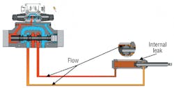
In the next example, an internal leak occurs in a cylinder that is used to hold a load in place with a system pressure of 2,250 psi. Figure 2 represents a cylinder in the hold condition — under pressure with zero leakage. If, however, fluid in the cylinder leaks past the piston seals, fluid flow will cause heat to migrate toward the leak point, Figure 3. This heat is generated by high-pressure fluid flowing through an orifice (the leakage path through the piston seals) to the low-pressure side of the piston without performing any work. Heat detected more than 2 ft from the heat point established in Figure 2 indicates that fluid flow is occurring. Internal cylinder leakage serves as the vehicle for this flow.
Any internal leakage of pressurized fluid generates heat because fluid energy that is not transmitted as mechanical power will be transformed into heat. Internal leaks transmit the lost power directly into the downstream fluid flow, which increases the temperature of the downstream fluid. The result is that the temperature exiting the cylinder exceeds that of the fluid entering it.
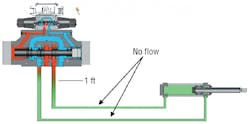
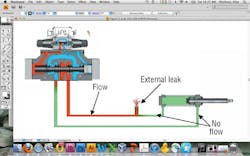
With external leaks, the heat transfers lost power directly to external environment. But some heat does transfer to the tubing leading to the leak, Figure 4. Depending on the amount of the leakage flow, the tubing’s outer surface temperature will increase closer to the leak point. However, at some point past the leak, approximately 1 ft in Figure 4, temperature returns to ambient because flow is (or should be) static.
Again, fluid flow is the main vehicle that transmits heat to piping surfaces and housings. Furthermore, a pressure drop across a leak path or orifice will increase the downstream fluid temperature by converting unused power into heat. From these two facts, we can approximate the actual fluid flow based on the temperature difference across the pressure drop.
Quantifying Leakage
Ideally, temperature measured across a cylinder should be static relative to flow. But in actuality, a temperature differential exists. In Figure 4, for example, assume temperature at the pressure port is measured at 141 °F, and 151° F at the tank port. This clearly shows a temperature rise of 10° F.
Using ∆T in° F and the pressure differential (∆P) in psi, the flow through the orifice (leak path) can be approximated. From the familiar equation for hydraulic horsepower, at 2,250 psi, a flow of 0.7623 gpm would produce 1 hp, which is 2,546 btu/hr. From standard conversions, we can calculate that 1 gpm of water is equivalent to 8.345 lb/min, or 500.7 lb/hr. Furthermore, if we define the specific gravity of hydraulic oil to be 0.90, and specific heat as 0.45, we can calculate heat generation:
btu/hr = m × c × ∆T.
Plugging in known values and solving for ∆T:
∆T = 15.9° F.
Using 15.9° F as a slope, any change in ∆T can be related directly to a change in flow based on a set pressure drop. Therefore, to approximate the fluid volume of an internal leak at 2,250 psi:
1. Define the flow required to generate 1 hp across an orifice at a specific pressure drop.
2. Find the temperature differential in °F at 2,546 btu/hr (1 hp) input using the flow value in gpm defined in Step 1.
3. Measure the temperature difference across the inlet and outlet ports of the cylinder. Use the actual measured ∆T in °F to alter the input power based on 1 hp being equal to 15.9° F at 2,250 psi.
4. Recalculate the new flow in reference to the new horsepower value.
The heat transfer discussed so far is a constant value relating to flow across two points. This does not account for the heat transfer through system piping and components. It also does not account for the heat transferred through reservoir walls or heat exchangers. It basically defines two set points of temperature in close proximity to an internal or external leak. By setting two temperature points across a cylinder or across a line, a constant inlet-to-discharge temperature difference can be found. Using that difference, you can calculate internal or external leakage.
Heat Detection Identifies Leakage
To actively trace heat through a system requires knowledge of how the valves in a circuit function and how many times they function per unit time. The use of an infrared heat gun for troubleshooting is mainly centered on finding internal or external leakage in components or, in some cases, improperly set or faulty pressure control valves.
The detection of heat, regarding internal leakage, can reveal seal wear before it becomes excessive. This allows replacing seals during normal scheduled maintenance, rather than waiting for leakage to become so severe that it slows down production enough to justify interrupting production to allow replacement. Heat from external leaks — even if they are relatively inaccessible — can reveal the location and severity of problems, such as loose or misaligned fittings, before they result in excessive fluid loss.
Identifying internal leakage in a 2-position valve is labor intensive using conventional troubleshooting techniques. Because the valve directs the cylinder to the end of its stroke and holds it there with a constant flow of pressurized fluid, heat transfer in the cylinder lines can quickly reveal internal or external leaks and allow for scheduled maintenance repairs.
In a 3-position valve, heat reveals leakage only when the cylinder is moving. Cylinder drift with the valve in neutral defines the occurrence of a leak in the cylinder or the control valve. Some amount of leakage should be expected with spool valves because this leakage provides lubrication to prevent stick-slip operation (stiction) of the spool. Often, a pilot-operated check valve is used in combination with a 3-position valve to hold a load more positively. The pilot-operated check valve changes the center condition of the valve to P blocked with A and B ports routed to tank. Any leakage from the P port goes directly to tank, which causes a heat rise in the directional control valve and the tank line.
The number of times a function cycles per unit of time period determines the distance heat is transferred to the piping from the directional control valve to the cylinder. System functions may be defined as continuously operating, intermittently operating, and static in reference the cycling of one product through an operation.
Normal Heat Generation
A thorough knowledge of how a system should operate is essential because all hydraulic systems generate heat. So knowing how much heat a system is supposed to generate allows determining when heat is excessive, and, therefore, leakage is occurring. Substantial wasted power is designed into many systems, and these systems use heat exchangers to remove the excess heat.
This wasted power is caused by internal leakage of components, pressure reducing valves, bypass flow at high pressure, and friction from normal motion to move a load. Most pumps and spool-type directional control valves operate using metal-to-metal clearances and depend on some leakage to form a lubricating oil film.
Leakage across the internal lands of directional-control valves is usually low — normally is measured in drops or in.3/min per land or per valve. This heat, from normal leakage, generally should not propagate more than about 2 ft from a component. This is why it is important to analyze system heat periodically, especially when a system is new or recently remanufactured. Storing heat distribution data of a new system establishes a baseline that can be used for comparison during subsequent studies.
Power Loss from Closed-loop Control
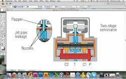
The greatest heat loss designed into a system may come from the use of jet-pipe or flapper-nozzle servovalves and proportional valves in closed-loop motion- and pressure-control applications. These valves require a constant flow in their pilot sections directly relating to a constant power loss. Essentially, the valves need a source of constant pressure so they can react quickly to changing load demands. The potential must exist to move the load from zero to maximum velocity at a prescribed maximum acceleration. The problem is, during periods when the load demands less than full flow, the excess energy potential — which can be substantial — goes unused. This unused energy generates heat.
The primary source of heat generation generally occurs whenever system pressure is elevated beyond that required by the load. However, using a pressure-reducing or a pressure-reducing-and-relieving valve in a circuit theoretically does not generate any significant heat during a static flow mode of operation. Significant power is lost only during a fluid flow condition and is directly related to the set pressure drop of the valve.
Power Loss in Flow-control Valves
There are three primary circuits for controlling the speed of a cylinder or other type of actuator: meter in, meter out, and bypass. All three methods restrict flow, which creates a pressure drop that wastes power and generates heat. Heat distribution for meter-in and meter-out is shown in the Figures 6 and 7.
Meter-in flow control causes a pressure drop from the system pressure to the moving cylinder load pressure, which generates heat downstream of the flow control valve. A meter-out circuit, on the other hand, generates heat past the flow control, toward the directional control valve, and, finally, to tank.
With a meter-in circuit, as the cylinder load decreases, the power lost will approach the power drawn. Although the power loss is significant, heat generation is relatively low because this is not a constant-flow condition. The power loss will, however, increase the surface temperature of the piping downstream of the flow control valve. The amount of temperature rise will relate directly to the number of function operations per unit of time and the differential between the fluid in the tubing and ambient.
Power Loss in Pumps
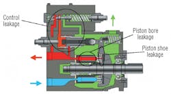
Internal leakage in a pressure-compensated piston pump is directly related to piston and control leakage at system pressure. Lost mechanical and hydraulic power is converted to heat and returned to the reservoir through the pump’s case drain. Depending on the compensation pressure, heat generation can raise the temperature of the pump case substantially.
For example, a large pressure-compensated piston pump leaking 0.5 gpm internally at a system pressure of 2250 psi would undergo a temperature rise of 9° or 10° F. The temperature would be even higher by taking mechanical losses and fluid compression into account. The same pump operating at 4500 psi would see a temperature increase of 42° F.
As a pump wears, leakage, naturally, increases. If the leakage in this same pump increased to 1 gpm, then the resultant temperature rise would be more than 20° F at 2250 psi and 80° F at 4500 psi. These figures can all be calculated by plugging in the appropriate values into the equations appearing below and on page 50.
Power Loss in Pressure-control Valves
A relief valve in a pump’s pressure compensation circuit is a static device that passes no flow except for minimal spool leakage. However, the valve does react to higher pressures that may approach or equal its opening, or cracking, pressure. It is extremely important to set the opening pressure of a relief valve at least 10 to 15% higher than system pressure. The main reason is because any relief valve, depending on its manufacturer, has a total non-bypass reset pressure that is a percentage of cracking pressure.
If a pressure compensated pump is set for 2250 psi, then the system relief should be set for at least 2600 psi. If the valve has a 10% reset value, or 90% of cracking pressure, then the valve will open at 2600 psi and fully close at 2340 psi when pressure drops. If not set properly, the valve will generate substantial heat. A vented relief valve normally loses power only when operating in its vented mode. The power loss, in this case, is directly related to a relatively small pilot flow across the valve vent section.
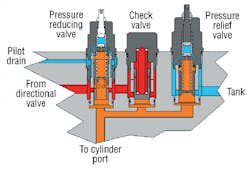
Combining a pressure reducing with a pressure relief valve in a function also can cause substantial power loss if the reducing valve is not set properly. If possible, a pressure reducing-relieving valve should be used. Technicians must be extremely careful when changing the pressure reducing valve setting. The pressure relief valve must always be set to a value 15% above that of the pressure-reducing valve. Improper settings will lose a great deal of power and, consequently, generate substantial heat.
Heat Test Point Positions
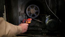
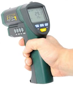
Temperature may be measured on the surfaces of pipe, tubing, and other components by many methods, but the most convenient is to use a heat-detecting gun. The heat gun is fairly accurate if used consistently in reference to distance from the object being tested. When making measurements, be sure to position the gun a consistent distance and angle relative to the target area.
Assume the target is a valve manifold. It will have at least one inlet pipe, tube, or hose (pressure line), one return line and, often, one drain line. Select a heat test point on each line approximately two feet from the manifold, and mark the inlet, drain, and tank lines with paint to establish three test points.
Examine the drain test point for heat (flow), which would serve as an indication of internal leakage in the directional valve’s pilot sections. The inlet and tank test points will indicate the internal and external leakage flow for the entire manifold assembly and all combined functions.
Next, select a heat test point approximately two feet from the manifold and mark both lines leading to an actuator with paint lines to establish two test points per function — two for the A line, and two for the B line. Select one heat test point in each line as close as possible to the actuator, and mark a paint line on the A and B port lines. Ensure that the test point only indicates pipe or tubing temperature, not heat radiating from nearby sources. A wide temperature difference between these two points serves as a possible indication of internal or external leakage.
Two additional test points should be established; one on the pump discharge line and one on the main return line to each power unit. These two points will monitor heat into the system valve stands and heat out of the system valve stands. The reservoir temperature can be checked, but it is not an accurate method of determining leakage because heat exchangers offset temperature increases. When the temperature in the reservoir rises above recommendations, a serious fault already exists, such as internal leakage in one or more components or a clogged heat exchanger.
Initially, it is advisable to make a temperature map of a system at startup. This will serve as a reference for subsequent test readings. To avoid any confusion, two maps should be created, one with equipment running and one with equipment down or after having run in standby more for two hours. The date of the original mapping should be recorded along with the ambient temperatures near the test points.
Note that a number of conditions may alter readings from the infrared heat gun. First, because most dirt is a poor conductor of heat, buildup on component surfaces tends to act as insulation. This causes the exterior temperature of the dirt buildup to be lower than the actual temperature of the pipe or tube OD. The same is true for scale and other contaminants that accumulate on the inner surface of the pipe or tube. Not only does this scale cause the outside of the pipe or tube to be cooler than the fluid inside, but if thick enough, a layer or scale can restrict flow enough to raise fluid temperature.
In both cases, this insulating layer tends to make the fluid retain heat. The same is true for hose, which also tends to provide insulation. Therefore, pipe, tubing, and hose runs may carry heat over a longer distance than they would if pipe or tubing were clean inside and out. Because the elevated temperature occurs over a longer distance, this condition may give the impression that internal leakage is occurring when it actually isn’t.
This further reinforces the practice of keeping hydraulic systems clean. Keeping both the interior and exterior surfaces clean promotes cooling by allowing heat to transfer through the pipe or tube to the surrounding area. Of course, keeping the hydraulic fluid as clean as is practical is always a good idea to maximize performance, reliability, and service life.
James R. Mollo, deceased, had been president of Hydraulic Design Consultants, McMurray, Pa., at the time the manuscript for this article was submitted.
About the Author

Leaders relevant to this article:
