Bulk Modulus: What is it? When is it Important?
Download this article in .PDF format
Despite the frequent assumption that hydraulic fluid is incompressible, the fact remains: All fluids have some degree of compressibility. Granted, fluid compressibility may be neglected in systems that do not require tight control of response and where operating pressure and fluid volume are moderate. However, when applying high pressure to a large volume of fluid, a significant amount of energy can be expended to compress the fluid — essentially squeezing the fluid's molecules closer together.
The result can be delayed response — a loaded actuator may not move until upstream fluid has been compressed, and the energy stored in the fluid may cause the actuator to continue moving after its control valve has closed. Bulk modulus is a property that indicates the compressibility of a fluid. With many of today's hydraulic systems operating at pressures 5000 psi and higher, ignoring bulk modulus can compromise response time of a system.
Applied pressure should directly affect the action of the system rather than compress the fluid. This is why it is so important to design systems with as little fluid as possible beween the control valve and the actuator.
What is bulk modulus?
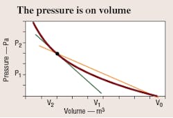
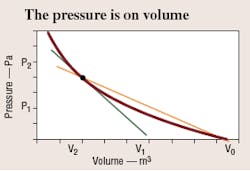
Most substances diminish in volume when exposed to a uniform, externally applied pressure. A typical plot of volume, V, versus pressure, P, is shown in Figure 1. The curve shows that volume of the fluid is a function of applied pressure, compressibility of the fluid, k, and initial volume of the fluid, V0:
V = f (P, V0, k)
V0 = initial volume, in, l, or m3
P = pressure, psig, Pa, or bar
k = compressibility, usually negative, in.2/lb
(V - V0) ÷ V = specific volume, commonly used for x-axis
The term bulk modulus usually means the reciprocal of compressibility and defines the slope of the curve when plotted against specific volume, Figure 1. Because specific volume is dimensionless, units of bulk modulus are the same as pressure — psig (bar, Pa, N/m2). Thus, the bulk modulus is a measure of resistance to compressibility of a fluid. A flat slope signifies a fairly compressible fluid having a low bulk modulus. A steep slope indicates a stiff, or only slightly compressible fluid.
Defining bulk modulus
The plot in Figure 1 is not a straight line, so its slope changes from point to point. Two common methods are used to define the slope, or bulk modulus1:
Secant bulk modulus is the product of the original fluid volume and the slope of the line drawn from the origin to any specified point on the plot of pressure versus specific volume (the slope of the secant line to the point).
Mathematically, secant bulk modulus, BS, is:
BS = (V0 × P) ÷ (V0 –V)
Tangent bulk modulus is the product of fluid volume at any specified pressure and the derivative of fluid pressure with respect to volume at that point (the slope of the tangent line to the point). Mathematically, tangent bulk modulus, BT, is:
BT = V0 (dP/dV)
Before giving some typical values for bulk moduli, we must take one more variable into consideration, namely, temperature.
Temperature and bulk modulus
Temperature is important because a fluid compresses as its temperature rises. As the temperature rises, the fluid attempts to expand, which, in turn, creates additional pressure. This can occur rapidly or slowly. Compressing the fluid very slowly allows generated heat to dissipate. This bulk modulus is called isothermal (constant temperature) bulk modulus. Adiabatic or isentropic bulk modulus occurs by compressing the fluid rapidly and measuring the pressure — even though it results from both compression and thermal expansion.
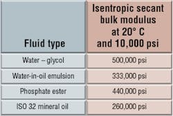
Because we are concerned with rapidly moving, tightly controlled systems, most hydraulic applications are considered isentropic. Therefore, most of the bulk moduli discussed here are isentropic. Table 1 shows values of isentropic secant modulus for some typical hydraulic fluids at a fixed pressure and temperature.
Effect of air on bulk modulus
Designers should be cautious before using published bulk modulus values. The values usually are determined by laboratory methods that take special precautions to degas the fluid before it is trapped and compressed.
However, hydraulic fluids typically become aerated in use. Aeration has a significant effect on bulk modulus because air is much more compressible than oil. George Totten2 discusses estimating the effects of air in oil on compressibility and bulk modulus. Also, realize that the solubility of air in fluids increases with pressure. Air dissolved in a fluid at high pressure can form bubbles when pressure drops — a phenomenon that can cause cavitation.
Predicting bulk modulus
Several sources are available for predicting the bulk modulus of hydraulic fluids2,3.
Volume lost in pumps and actuators — The output of a pump or the positional relationship of master and slave cylinders varies with the bulk modulus of the fluid. In the case of pumps, the percentage volume loss in the output is seen as a loss of horsepower. For master-slave cylinders, the volume loss is seen as a reduced stroke from the slave.
Stopping a moving load — If a cylinder moves a load at a uniform velocity (that is, constant flow to the cylinder), the cylinder has momentum that the fluid and the system must absorb when a valve controlling upstream and downstream flow is suddenly closed. The downstream fluid pressure will rise from some nominal value to some peak pressure as energy is absorbed. Assuming the cylinder and hydraulic lines to be rigid, and a linear rise in pressure, the fluid's bulk modulus will determine peak pressure. Thus, for a specific maximum pressure, the stiffer the fluid, the less energy is absorbed and the less overshoot. Fluids with higher values of bulk modulus have less energy absorption and less piston overshoot, which translates to better position accuracy.
Fast load reversals — Because most fluids are compressible, the fluid in an actuator must be compressed before the cylinder or piston will move a load. In other words, an amount of fluid equal to the compressed volume must be added to an actuator before a load will move. Because this process does not do useful work, it is lost work:
WL = f × d where WL = lost work
f = force
d = distance
Distance refers to an increment of cylinder stroke, so:
WL = âP × âV0
where âP = change in pressure
âV = change in volume (increment of stroke × piston area)
But âV = âP × (V0 ÷ B), so:
WL = (âP2 × V0 ) ÷ B
To calculate lost power, divide by time:
WL = (âP2 × V0) ÷ (Bt × 6600)
Because power loss can be significant at higher pressure ranges, let us examine a typical 3000 psig system, that is, âP = 3000 psi.
hpl = (1363 V0) ÷ (B × t)
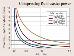
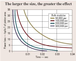
It is now possible to plot lost horsepower versus time for 1 in.3 of cylinder volume for various bulk moduli, Figure 2. Lost power increases as cylinder size increases and response time decreases.
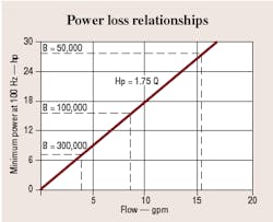
Figure 3 illustrates lost power versus response rate for various bulk moduli. The loss in power may look relatively small until we consider an average cylinder. If we assume a bulk modulus of 200,000 psi, a response of 100 Hz, and a stroke of 10 in., the power loss is 6.75 hp / in.2 of ram area. Figure 4 relates power loss to total system power available. For example, a 3000-psi, 3.8-gpm system that can supply 6.75 hp cannot move a load at 100 Hz with a 1-in.2 piston because all the power is used in compressing the fluid.
Resonance of hydraulic systems
The natural frequency of a springmass combination is:
ƒ = (1 ÷ 2π) × (kg)1/2 ÷ W
Where: ƒ = frequency, Hz
W = weight, lb
k = spring rate, lb/in., and
g = acceleration due to gravity, 32.2 ft/sec2.
To equate this to a hydraulic system, we only need to substitute bulk modulus for spring rate. Thus, a low modulus also lowers the natural frequency of a system. For example, if 1% air content changes the bulk modulus by 50%, its natural frequency decreases by 30%. This greatly reduces the stability of the system.
Why bulk modulus is important
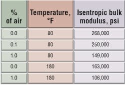
We can conclude, then, that the absolute value of the bulk modulus of a fluid can seriously affect system performance in relation to position, power level, response time, and stability. Two factors that figure prominently in the control of bulk modulus are fluid temperature and entrained air content. For example, Table 2 shows that raising the temperature of commercial hydraulic fluid by 100° F alone reduces its bulk modulus to 61% of its room-temperature value. Table 2 also indicates that introducing 1% air by volume reduces the bulk modulus to 55% of its room temperature value. If these two conditions occur simultaneously, the net effect is to reduce the bulk modulus by 67%.
In view of today's requirements for higher power and response time, it is more important than ever to pay attention to bulk modulus.
References:
1. ASTM D6793 "Standard Test Method for Determination of Isothermal Secant and Tangent Bulk Modulus," ASTM International, West Conshohocken, Pa.
2. Handbook of Hydraulic Fluid Technology, edited by George E. Totten, Marcel Dekker, Inc., 2000.
3. Hydraulic Fluid Power — Petroleum Fluids — Prediction of Bulk Moduli, ANSI.NFPA T2.13.7 R1-1997 (R2005) National Fluid Power Association, Milwaukee.
