Air entrainment — how it happens, how to avoid it
One trend in industrial manufacturing is for systems, as well as components, to be designed in a more compact fashion.
The benefits of smaller machinery are obvious — economy of materials, less energy consumption, less square-footage required. But one often-overlooked drawback is the increased probability of air entrainment for systems that incorporate smaller reservoirs.
Bubbles in working fluids greatly influence the performance of hydraulic systems and may cause major problems, such as bulk modulus change, cavitation and aeration, degradation of lubrication, noise generation, oil temperature rise, and deterioration of fluid quality. When bubbles in fluid are compressed adiabatically at high pressure, the temperature of the bubbles rises sharply, and the surrounding fluid temperature also rises. Thus, it is important to eliminate the bubbles from the fluid to preserve its quality, system performance, and to avoid possible damage of the components.
Bubbles vs. foam
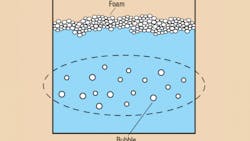
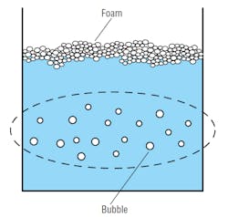
What is a bubble? It is a general term that can refer to various phenomena that occur at the surface of a gas suspended in a fluid. However, for technical use, the terms bubble and foam must be strictly defined. In this article, bubble means small gas particles entrained and dispersed in the fluid, Figure 1. Conversely, foam is comprised of many gas pockets surrounded by a thin film and is created when fluid is mixed rapidly with air from the free surface. It occurs when bubbles in the fluid become enlarged and rise to the fluid surface, or when fluid is ejected into a reservoir.
Troubles caused by bubbles
Foam causes problems when it overflows the reservoir. In such cases, the problem may be easily solved by adding ester or silicon oil to the fluid as an anti-foaming agent, or by repairing the equipment to eliminate foam generation.
Bubbles can be created in many ways. Following are sources of air ingression, where bubbles may be generated in a hydraulic system:
Release of dissolved air — All hydraulic fluids contain an amount of dissolved air, which can be released when the pressure is decreased rapidly. This can occur at valves and orifices, as well as where the fluid returns to the reservoir.
Mechanical introduction — Entrained air can be introduced at points in the system where there is a vacuum, such as leaks in the pump suction line.
Improper bleeding — When initially filled, the hydraulic system will contain air in all forms (free, entrained, and dissolved). For proper operation, the system should be properly bled to remove air.
Improper addition of make-up fluid — Air may be entrained in the fluid if splashing occurs when fluid is added, or if the added fluid causes increased agitation in the reservoir.
Contamination — One common source of increased air entrainment and foaming is fluid contamination by surface-active compounds. Alternatively, the fluid may be contaminated in such a way that causes precipitation of the antifoam or air release agent, resulting in significant increases in air entrainment.
Improperly designed reservoirs — The overall dimensions should enclose a sufficient volume of oil to permit air bubbles and foam to escape during the resident time of the fluid in the reservoir. The depth must be adequate to ensure that during peak pump demands, the fluid level will not drop below the pump inlet. The pump should be mounted below the reservoir so that a positive pressure is maintained at all times. This is most critical when water-based hydraulic fluids are used, as these fluids have a higher specific gravity as well as a much higher vapor pressure than mineral oil-based fluids.
Baffles should be provided to prevent channeling of the fluid from the return line to the pump inlet. A breather filter cap should be provided to admit clean air and to maintain atmospheric pressure as fluid is pumped into and out of the reservoir. With water-based hydraulic fluids, a pressurized reservoir is recommended to compensate for the pressure drop at he pump inlet due to the vapor pressure of the fluid.
The bubbles themselves often are created at the following locations or by the following conditions within the system:
● where there is a pressure drop,
● at a throttle or orifice,
● at a branch or pipe joint,
● from a valve opening and closing rapidly,
● from shock waves, due to sudden closing of valves or cessation of pump operation, and
● due to pressure drop at the pipe end, due to sudden opening of valve.
Bubbles entrained in the fluid can create many problems in hydraulic systems, such as:
● acceleration of oil degradation by oxidation,
● decreasing lubricity caused by an air emulsion,
● reduction of thermal conductivity,
● cavitation erosion,
● higher noise emission,
● increase in compressibility and decrease in dynamic characteristics, and
● decrease in pump output efficiency.
Dealing with foam
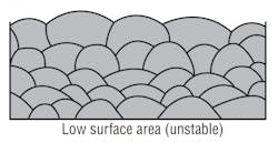
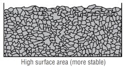
Foam is a dispersion of an entrapped gas in a liquid where air bubbles form a separate layer on the surface of the fluid and are separated by relatively thin fluid films. Foam stability can vary in a hydraulic system, Figure 2 and Figure 3, depending on surface area, surface tension, viscosity, and the concentration of the contaminant.In the absence of a defoamer, all foam will eventually end up as a stable high surface area foam. However, if the foam continues to grow, displacing the liquid phase, it may reach the pump inlet, causing cavitation.
The only way to break this high surface area foam is to introduce a defoamant (i.e. a silicone) into the surface film that stabilizes the foam, Figure 4(A). The defoamant then spreads throughout the surface of the film, surrounding the air pockets, Figure 4(B). As the defoamant spreads, the shearing force causes a flow of the stabilizing film away from the gas bubble interface, resulting in a thinning of the interfacial film, Figure 4(C). This continues until the bubble ruptures, finally resulting in a release of the gas contained in the bubble, Figure 4(D).
Antifoam composition varies from single to multiple component systems. Single component systems are typically water-insoluble and surface active, since they must displace the pre-foaming surfactant in the interfacial film stabilizing the gas bubbles. Examples of single component systems include: fatty acids and their glycerides or ethoxylates and polypropylene glycols. Typically, this class of antifoams is used at concentrations of 0.1 to 0.4%.
A multicomponent antifoam system typically contains a dispersion of a mineral oil-based material, hydrophobic silica, and a surfactant, such as a fatty acid or alcohol ethoxylate composition in the fluid through- out the hydraulic system.
A bubble eliminator?
A bubble eliminator is a tapered-tube type device with a chamber of circular cross-section that becomes smaller (in relation to its length), and is connected to a cylindrical shaped chamber. Fluid with bubbles flows tangentially into the larger end of the tapered tube from an inlet port and forms a swirl flow that circulates fluid through the flow passage. The swirl flow accelerates downstream, and the fluid pressure along the central axis decreases downstream. From the end of the tapered tube, the swirl flow decelerates downstream and the pressure increases towards the out- let port. Bubbles are trapped in the vicinity of the central axis and collected near the area where the pressure is lowest. When backpressure is applied by a check valve or an orifice located at the downstream side of the bubble eliminator, the bubbles are ejected through a vent port. The dissolved gas in the fluid is also eliminated by extracting bubbles at the pump’s suction side under negative pressure.
Use of such a device may allow the hydraulic designer to gain the following benefits:
● a reservoir with lighter weight, smaller space, and lower cost
● slower fluid degradation, which extends fluid’s useable life
● prevent pump cavitation and noise
● requiring less fluid in reservoir, which reduces cost and increases safety
● shorter heating time in cold weather
● decrease in fluid compressibility
● easier contamination control, and
● simpler configuration of reservoir, with no baffle plate needed.
George E. Totten is senior research scientist and Roland J. Bishop, Jr. is a project scientist in UCON fluids and lubricants for the Dow Chemical Co., Tarrytown, N.Y. Ryushi Suzuki is president of Opus System, Inc., Tokyo. Yutaka Tanaka is a professor of engineering at Hosei University, Toyko. For a more detialed discussion, refer to SAE Technical Papers, 982037 — Bubble Elimination in Oil for Fluid Power Systems, by Suzuki/Tanaka/ Arai/Yokata; and 972789 — Hydraulic Fluids: Foaming, Air En- trainment, and Air Release — A Review, by Totten/Sun/Bishop. Either can be ordered from SAE by calling 412/776-4841 or visiting www.sae.org.


