Electrical and electronic devices control most fluid power circuits. Relay logic circuits, programmable controllers, or computers are common control methods. But another way to control pneumatic systems is with air logic. Air logic controls can perform any function normally handled by relays, pressure or vacuum switches, time delays, limit switches, or counters. The circuitry is similar, but compressed air is the control medium instead of electrical current.
Environments with high levels of moisture or dust are excellent places for air logic controls. No danger from explosion or electrical shock is presented by the air-logic system. Water can splash on the controls without affecting their operation. If there is an external explosion, the control media—clean compressed air—cannot ignite.
Some designers of pneumatic equipment prefer to use air-logic controls because only one utility service is needed to operate it. No electricity is necessary. This arrangement can be a selling point in user facilities where electrical and mechanical maintenance must be handled by different labor trades. Because there are no electrical devices involved, one craft works on both the air-logic circuit and machine parts.
Two basic roadblocks to using air-logic control are a lack of understanding of how the components work and an inability to read the special schematic drawings. If an air-controlled machine fails, few people know how troubleshoot it. Also, air-logic circuits with long conductor lines—more than 10 to 15 ft—may cycle noticeably slower than similar electrical controls. They cannot fill with and exhaust air as quickly as electrical signals travel. Finally, air quality must be above average to ensure consistent performance and long component life.
The components used for air logic controls are basically miniaturized 3- and 4-way air valves. The actions of these valves turn functions on or off, just as relays or switches do, then exhaust the spent signal. The symbols that were developed for air logic are similar to electronic symbols. In fact, some manufacturers use modified electrical symbols and ladder diagrams to show circuitry.
Basic Logic Elements
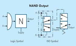
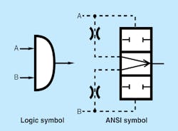
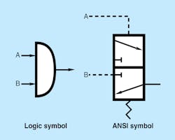
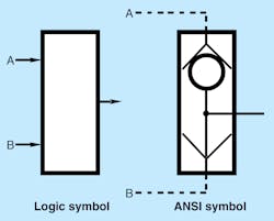
Following are text explanations of the functions of basic logic components, with illustrations using standard ANSI logic symbols and ISO graphic symbols of a comparable directional control valve.
An AND element must receive two input signals simultaneously before it passes an output signal. This ensures that two upstream functions are complete before there is a command to a downstream function. In other words, inputs A and B must both be present before an output action occurs. When using more than two inputs, AND elements are connected in series. The first AND receives signals 1 and 2, and the output of this element interfaces with an input to the second AND. The other input of the second AND receives a third signal, making three inputs necessary before an output action can occur.
Figures 1 and 2 show two types of AND elements. Some manufacturers supply passive and active types of elements but designate the passive AND simply AND, whereas the active AND is designated YES. The difference in the elements is that the passive AND element uses the lower of the two inlet ports as an output. In contrast, the active AND element has two inputs to achieve an output, but the designer has the choice of which input goes to the output. Using this feature can amplify a weak signal. The weak signal pilots the valve open while the through signal comes from a full-pressure supply. The YES is an active element.
A signal at either input port of an OR element (Fig. 3) produces an output signal. Another way of saying this is that either signal A or B will produce an output. A shuttle valve serves the same purpose as an OR element. Pilot signals from two different sources can pass through the OR to start the next function. An OR element differs from an in-line tee because an OR passes either input to the output but does not allow the inputs to pass to each other. OR elements can be stacked to accommodate more than two inputs. Use an extra OR for each input after the first two signals.
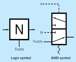
A NOT logic element (Fig. 4) is a normally open 3-way valve. An input signal to the Supply port will pass through the valve until there is a pilot signal at port A. Pressurizing port A blocks supply and exhausts the output signal to atmosphere through port B. As long as there is pilot pressure on the A port, NOT elements will block a signal or supply. NOT elements always return to a normally open condition when the pilot signal is removed.
A NOT element can simulate a limit switch to indicate that a cylinder is at the end of stroke. Pressure from the cylinder port goes to port A of the NOT, holding it closed. As the cylinder extends toward the work, pressure is maintained because of the meter-out flow control. When the cylinder contacts the work, the signal at port A exhausts, and the NOT opens to pass an output signal to start the next operation.
Note that the cylinder can stop at any position and the NOT’s output signal will indicate that motion has stopped—whether the cylinder stopped where it should be or is stalled by some other means. Because of this, take care when using a NOT to replace a limit switch.
On the other hand, this phenomenon can be advantageous when clamping different sized parts. Use a NOT element for applications where different work locations stop the cylinder.
CAUTION! Any pressure-control valve only responds to a pressure buildup. When a positive location must be identified, use limit valves.
Most manufacturers supply a different pilot ratio for a NOT element used as a limit switch. The valve function is the same but the pressure that shifts it is much lower. Some manufacturers build special NOT elements that mount directly in a cylinder port. A port-mounted meter-out flow control used in conjunction with this special NOT makes a compact installation.
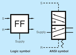
A FLIP FLOP (Fig. 5) is a double-piloted 5-way valve that directs supply air to either outlet port in response to signals at pilot ports S or R. (Supply air can be system pressure or a signal from another logic element.) The main purpose of a FLIP FLOP is to exhaust the first pilot signal to a directional control valve. Then a second signal to the valve’s opposite pilot port can shift it back. FLIP FLOPs are sometimes called MEMORY elements because they stay in the last shifted position even with no air supply. Whether the signal is maintained or drops out, output from the FLIP FLOP stays the same.
The S and R signal designations stand for SET and RESET. The SET signal shifts the FLIP FLOP for a function, and whether S is maintained or not, the element stays shifted. The RESET signal returns the FLIP FLOP to its original position until the next cycle.
Another use for a FLIP FLOP is to set up a new cycle allowing the operator to momentarily push the start buttons. This same FLIP FLOP can be installed to block unwanted signals and set up the circuit for cycle completion as required.
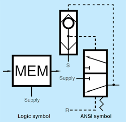
Figure 6 shows another valve actually called a MEMORY element. A MEMORY element is a normally closed 3-way valve with an integral shuttle valve. The MEMORY’s output air hold the shuttle valve shifted once it receives a SET signal. A momentary SET signal gives continuous pilot output. A RESET signal shifts the MEMORY element to normally closed and exhausts output air. Also, turning SUPPLY pressure off returns a MEMORY element to the start position.
In air logic control there are three different types of time delays. Fixed or adjustable time delays are common in both normally closed and normally open configurations. Some time delays use an orifice and accumulator chamber for delays as long as one minute. Some manufacturers use air-actuated diaphragms and orifices that eliminate inaccuracies due to system pressure fluctuation.
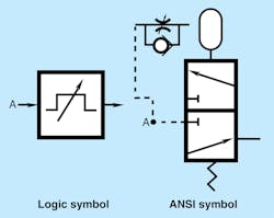
Figure 7 shows the symbol for a ONE-SHOT timer, sometime called an IMPULSE TIMER. A ONE-SHOT timer takes a signal and passes it on to the circuit. At the same time the input signal is going through an orifice to an accumulator chamber. The setting of the orifice and size of the accumulator gives a certain time delay before the normally open 3-way valve closes. After a ONE SHOT times out and closes, it remains closed as long as it has an input signal. Figure 7 shows an adjustable time delay before losing the output. Omitting the sloping arrow in the symbols makes it a preset time delay. Times range from a half second to two or more seconds on valves with preset time delays.
Many circuits use ONE SHOTs to eliminate opposing signals. When a valve receives a signal to extend a cylinder, it resists a return pilot signal to itself until loss of the first pilot. Using a ONE SHOT element drops the extend signal shortly after initiation. However, when the short duration signal meets a hard-to-shift valve, the time may not always be long enough to move the valve spool. When the valve does not have time to shift, the cycle stalls. For best results, use a FLIP FLOP to drop an unwanted signal after it performs its task.
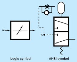
Figure 8 shows an adjustable, normally closed TIME-ON time delay symbol. A TIME-ON delay passes a signal through the element after timing stops.
A TIME-ON delay is a preset fixed timer without the sloping arrow. Most anti-tie down circuits use a fixed time delay. This forces the operator to actuate both palm buttons concurrently.
Assume an input signal is applied to blocked port A of the 3-way directional valve in Fig. 8. The same signal also passes through the meter-in flow control to fill the accumulator. After the accumulator is filled, pilot pressure shifts the 3-way valve, allowing air to pass on to the next operation. As long as the input signal stays on, the time delay stays open.
Some brands of TIME-ON delays use shop air to the normally closed port A of the 3-way valve while the signal to the timing section comes from another logic element or limit valve. This allows a strong passing signal to travel long distances or to quickly shift several other logic elements.
With an integral accumulator chamber, the time-delay length is usually between a minute and a minute-and-a-half. With additional external accumulators, time delays up to five minutes are possible. The repeatability of long time delays using accumulators is poor. However, diaphragm-type timers often can produce 3-minute delays with acceptable repeatability.
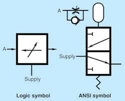
With a normally open 3-way valve in place of the normally closed 3-way valve, the function becomes a TIME-OFF delay timer (Fig. 9). An input to the SUPPLY port passes continuously to output until a set time after a pilot signal is received at port A. When A receives a signal, the time delay starts and continues until the accumulator fills and shifts the normally open 3-way valve to block the signal at SUPPLY and exhaust the downstream system. Adjustable and preset, non-adjustable TIME OFF delays are available. TIME-ON and TIME-OFF delays often are identical in appearance. The part number may be the only way to tell these units apart.
About the Author

Leaders relevant to this article:
