Multi-axial servohydraulics controls compaction press
The key to pressing multiple-level powder-metal parts and achieving uniform material density is to ensure that each segment of the part is compacted with the appropriate force. This level of control can't be obtained with mechanical presses because they apply the same force to the entire cross-section of a mold. Multi-axial hydraulic presses, however, can apply the appropriate force to varying cross sections of the part.
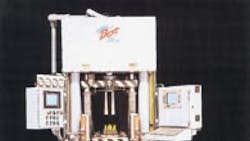
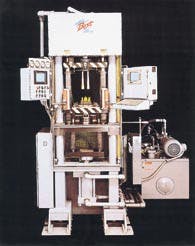
With a hydraulic press, the control authority and flexibility enable the press to adapt to fit the material rather than the other way around. Best Press Corp., Castle Hayne, N. C., incorporates a variety of off-the-shelf hydraulic and other components with industrial PC-based control software to offer a smooth transition from position-based to pressure-based servocontrol of up to six axes of motion simultaneously. Using the new hydraulic press, a compacted-powder part can be made for less than half the cost of a machined part.
Hydraulic press steps up
Uniform material (powder) loading is critical to achieve uniform density in the finished part. To this end, Best Press uses multi-stage, hollow-rod, and conventional double-acting cylinders to form a cavity in the mold. Powder is pushed into the cavity and then compressed by the cylinders into the shape of the part being manufactured. The powder has binders in it that, along with the pressure, hold the pressed part together. After the compression step, the part is baked (a process known as sintering) to impart strength and hardness to the final product. The process of forming products in this manner eliminates the expensive machining step used in traditional manufacturing.
The machine actually goes through multiple steps in the molding process. Each step is coordinated by a closed-loop control algorithm with cylinder position feedback provided by magnetostrictive linear-displacement transducers (MLDTs) and pressure feedback from pressure transducers. The steps are:
1. Go to fill position - During this step, the cylinders move to a home position for filling the cavity with powder. The lower main cylinder retracts downward and the top cylinders extend upward.
2. Material transfer phase - A feed shuttle extends to fill the powder cavity in a single operation. Next, the shuttle retracts as the upper cylinders extend downward to close the cavity. All cylinders move simultaneously into position to begin compressing the material. During this phase, velocity of the upper cylinders is precisely ramped down to avoid pushing material out of the cavity. As this step continues, the upper and lower cylinders come in contact with the material. The cylinders must all move simultaneously to displace the material equally and prevent the creation of voids in the mold cavity.
3. Compression phase - Once the cylinders extend to begin compressing the material, the control algorithm seamlessly switches from closed-loop position control to closed-loop pressure control for all axes. During the compression (or tonnage) phase, pressure is applied to each cylinder in a synchronized procedure so that all cylinders achieve peak pressures at the same time. This is the feature that allows the press to produce a part that has uniform density throughout.
4. Eject phase - After the compression phase has been completed, all axes must move simultaneously to eject the part. Care must be taken not to compress the part any further. The part is pushed up out of the die cavity by the lower cylinders, and the feed shuttle then comes forward as the upper cylinders retract out of the way to their home position, readying the press for the next cycle.
Shelf life
A major concern in the new system design was that the hardware be easy and quick to configure and reconfigure to support different press models and different types of powder stock. For flexibility and ease of programming, the design incorporates an industrial PC as the control and human-machine interface computer, and Visual Logic Controller software from Steeplechase software, Ann Arbor, Mich., to supervise and coordinate the process steps.
To connect the industrial PC to the rest of the system, Best Press engineers specified an industry-standard data interface that was already supported by a PC plug-in card and also well-supported by the control modules they would be using in the rest of the system. They selected a PROFIBUS interface card, which gives this standardized system expandability and high-speed (12-Mbaud) communications.
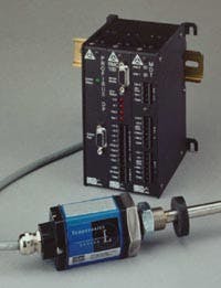
The heart of the control system is a pair of Delta RMC100 motion controllers, offering high-resolution position and pressure control, quick response, and easy programming and monitoring. Each RMC is capable of controlling up to eight position axes or four axes of both position and pressure. The Best Press design calls for two RMCs because six axes of synchronized position and pressure must be executed. Each RMC controller is a stand-alone module in a DIN rail-mountable box containing a Profibus interface, a CPU, and 16-bit analog input and position transducer interfaces.
Because the system must have fast response and very precise operation, hydraulic proportional valves that can respond to high-frequency input signals were specified. These valves, manufactured by Moog Inc., East Aurora, N.Y., have a zero-overlap spool to prevent any dead zone when shifting through the center spool position.
* they provide absolute position feedback; therefore, they do not have to perform homing functions at power-up or system reset* they exhibit non-contact measurement, so there are no moving parts to wear out,
* they are available with digital output, which greatly simplifies control electronics for this application, and
* their repeatability of measurements is very high, which ensures consistent high-quality production.
To simplify the design of the system electronics, the RMC motion controller comes with a standard MLDT interface. Two twisted-wire pairs connect directly from the RMC to each position transducer. For pressure feedback, each cylinder has a pressure transducer installed at both its rod and cap ends. This produces a signal representing differential force across the piston and accounts for the unequal areas on either side of the piston.
The press also has interfaces for digital I/O functions, including operator pushbuttons and discrete solenoid valve control (for hydraulic loading and unloading and control of functions requiring only on/off operation).
Getting with the program
After verifying communication between the hardware modules in the system, a process sequence was programmed into the Visual Logic Controller software to handle communications between the PC and motion controllers. As a hydraulic motion profile is set up, the PC downloads motion sequence instructions into the RMC. For example, the motion profile for extending the upper ram cylinders down to initiate the compression phase involves multiple steps that were all loaded into the RMC simultaneously.
The RMC is programmed using convenient tables of information displayed on an operator screen. Each table contains command fields that describe how each of the six axes are to move. For example, when an RMC is in the position control mode, the following information is put into the table to give a command to move a hydraulic cylinder to a particular position:
* a mode word - information on how to interpret the other fields and what inputs to monitor* the rate of acceleration when motion begins
* the rate of deceleration to terminate motion
* the maximum allowable speed
* the final position of the hydraulic cylinder, and
* the command to go.
In the pressure mode (when the motion controller is receiving its inputs from pressure transducers), the controller's function tables provide information about pressure setpoints. These setpoints define when the controller should enter the compression phase, the pressure ramp rate, and when it should exit the pressure mode. All this provides a smooth transition from position control to pressure control using the same proportional valve.
The speed and duration of the hydraulic cylinders' motion and the pressure profiles in the compression phase are tuned by changing the numbers stored in the table entries. The RMC allows an attached computer to interrogate its internal function table and sensor inputs. This allows comparison of actual and desired motion results.
Each command in the motion controller's function table also has a link to the next command to be performed. Therefore, the motion controller can execute a sequence of operations without further intervention from the controlling computer. Links between active motion commands normally would introduce delays or additional testing or setpoint criteria. But because the RMC can execute multiple motion steps in sequence and test conditions, the PLC or PC that controls the RMC is relieved of these tasks.
The RMC continuously monitors its input conditions as frequently as once every msec. It uses two PID loops together with a smart switching algorithm to control the position or pressure of an axis. Each servo-drive output of the RMC commands one zero-lapped proportional valve, which controls either position or pressure of an axis. While controlling in the pressure mode, the RMC dithers the signal to the valve to cause the small change in spool position required to maintain the desired force at the cylinder. Controlling position and pressure eliminates the extra valves and plumbing otherwise needed for pressure regulation in other designs. Furthermore, the RMC's two PID loops and graphical tuning tools allow separate tuning of position and pressure for precise control in both modes.
Because the press's motion sequences exist in software, they are easy to reconfigure. Therefore, the press can produce different parts or use different materials, such as ceramics or any of several metal powders. Every time changes are made, the PC sends new profile information over the PROFIBUS to the RMCs. As a safety check, the contents of the motion table are read back by the PC to make sure that the correct information was loaded. Changing setpoints can be done on the fly to adapt the system to changing environmental conditions, such as temperature and humidity of the press room.
The transducer interface
To determine cylinder position, the RMC interface sends an interrogation pulse to the MLDTs, which respond with a feedback pulse. By measuring the time between the interrogation and response pulses, the RMC calculates the position of the piston within the respective cylinder. The MLDT produces the feedback pulse at 9.1 msec/in., so the RMC can calculate cylinder position at a resolution of better than 0.001 in.
Triggering the MLDTs directly from the RMC interface yields two advantages. First, not using an internal MLDT interface eliminates the time delay that this intermediate device could introduce. Second, by interrogating the transducer in the RMC, the position sample will be synchronous to the RMC's control loop. If the transducer was interrogated internally, it would generate gate pulses at a rate proportional to the length of the rod. Instead, all four MLDTs are triggered by a simultaneous interrogation pulse. If each MLDT used its own interrogation circuit, synchronizing the interrogation pulses would add complexity to the servoloop and slow it down.
The pressure transducers are mounted in the ends of each cylinder in a location that is least affected by oil flowing into or out of the cylinder and in an orientation that prevents trapping air in the cylinder. The pressure-control algorithm is a function contained in firmware. When the press is being programmed, the operator enters a tonnage setpoint, which is loaded into the function table for the RMC motion controller. When in operation, the RMC controls pressure to this setpoint.
Overcoming design challenges
One of the main challenges in implementing this design was the coordination of the six independent position/pressure control axes of the machine. The control task was partitioned between two RMCs to handle the six motion axes. Separate sets of program sequence information and commands travel over the PROFIBUS between the PC and each motion controller. However, the two motion controllers need to be synchronized with each other, so the parallel branch and merge capabilities of the control software simultaneously initiate the execution of two different sets of motion control commands over PROFIBUS. To further ensure that their activities are synchronized, the RMCs signal each other using their on-board digital I/O.
During the development process, Windows-type setup and tuning software for the RMCs was used to adjust operation of the machine. This software continuously monitors and graphs the actual position and pressure data from both RMCs. The raw data from the sensors is scaled and translated automatically by each RMC, which allows for sensor readings in meaningful terms. For example, the RMC reports data in inches of position or pressure in psi instead of as raw readings from the transducers. This data can also be used for statistical process control without further manipulation.
The press is programmed electronically to dramatically shorten setup time and to adapt to the materials being formed. With its smooth transition from position- to pressure-based control, the system offers tighter control and more flexibility than mechanical presses, with higher-resolution linear positioning than if hydraulic control with discrete directional valves had been used.
Don Denman is senior application specialist, Delta Computer Systems, Inc., Vancouver, Wash.; Wayne McNeil is field engineer, Tri-Tech Engineering, Saginaw, Mich.
About the Author

Leaders relevant to this article:


