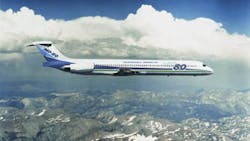
The MD-80: hydraulics simple, reliable, and easy to operate
This file type includes high resolution graphics and schematics when applicable.
The DC-9 aircraft was designed in the early 1960s and introduced into commercial service in 1965. The original version had a maximum takeoff weight of 76,000 lb and could carry 80 passengers. Growth versions of the DC-9 increased the aircraft capacity to 121,000 lb maximum takeoff weight in the Series 50. Today’s airplane, the MD-80, at 160,000 lb, has a takeoff weight more than double that of the first DC-9s.
The original aircraft hydraulic design principles were to keep the hydraulics:
• simple
• reliable, and
• easy to operate and maintain.
The concept of the DC-9 hydraulic system was very simple: a minimum number of components and maximum of efficiency. The DC-9 required only half as many hydraulic components as were used in the DC-8, and substantially fewer than used in contemporary small jets. Simplification of mechanisms paid off in a corresponding improvement in reliability and ease of operation and maintenance.
Component improvement
Historic hydraulic system problems were analyzed and either solved or greatly minimized. For example:
• packing failure problems were virtually eliminated by Douglas’ pioneering in the development of ethylene propylene compounds for use with phosphate ester fire-resistant fluid
• backup rings used with all static and dynamic seals greatly reduced O-ring nibbling
• elimination of positionable, universal-type fittings in boss connections increased reliability
• while flareless-type tube fittings were offered as an optional feature, flared fittings were recommended as standard and accepted by virtually all DC-9 operators
• corrosion-resistant tubing was used in all pressure applications and in return lines smaller than in OD
• coiled tubing replaced hoses where possible
• where hoses were used, they had Teflon-lined, stainless steel wire braid construction, and
• careful attention to design detail greatly reduced the ever-present problems of system surges and corrosion.
Family overview
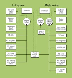
The family of DC-9 aircraft has two independent and completely separate hydraulic systems, Figure 1. Fluid from one system is never allowed to mix with fluid from the other. The systems are known as Right or Left; each receives its primary power from an 8-gpm variable displacement pump mounted on the respective right or left engine. The Right system is also equipped with an 8-gpm electric-motor-driven auxiliary pump. The Left system received auxiliary power from two fixed displacement, mechanically connected pumps to provide a reversible drive between the two systems. Each system also contains a hand pump for ground servicing.
The engine pumps are dual-range-compensated and may be selected to either 3000 psi or 1500 psi. During normal takeoff and landing operations, all pumps are switched ON and the engine pumps are in the 3000-psi mode. During cruise, after cleanup, the electric pump and reversible pumps are switched OFF and the engine pumps are switched to the 1500-psi mode. This reduced pressure greatly increases component life.
Hydraulic systems
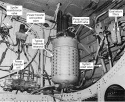
The systems are as air-free as modern technology permits. Closed system, boot-strap reservoirs are used with ample air trap volume, and simple pushbutton bleeding valves purge air quickly, Figure 2.
Excellent return filtration is achieved with identical 15-µm absolute disposable-element system filters. All return fluid is filtered as it enters the reservoir. Fluid from the electric and engine pumps is filtered on the pressure and case drain lines. All fluid entering the system is filtered, whether a ground service connection or hand pumps is used. Each filter incorporates a visual, differential pressure indicator pop-up button to signal when an element must be replaced.
The hydraulic and landing gear systems for the DC-9 family have changed as the aircraft grew. Series 10 established the baseline design. Series 30 added a hydraulically-driven wing leading edge slat system, increased reservoir capacity, and strengthened the landing gear. Series 40 retained the series 30 hydraulic system but changed the wing incidence angle. The size of the main landing gear was increased, repositioned in the wing, and used a new rolling assembly. Series 50 required only a change to the elevator system to increase hinge moment capability.
The MD-80 represents more substantial change. The wing span was increased, adding to both the leading edge slats and trailing edge flaps. The main landing gear is re-positioned in the wing, has a larger diameter and length, and a new rolling assembly. Also added is a new inboard ground spoiler system. Reservoir capacity was increased again and most hydraulic components were re-designed or re-located. The auxiliary pump was changed to the DC-10 air-cooled unit; a new reversible power transfer unit was added. Through all of the system evolution, the engine hydraulic pumps remained the same.
Subsystem design features
This description of some hydraulic features on the 80’s subsystems emphasizes designed-in safety and redundancy of components and subsystems, and also included mechanisms and subsystems that fail safe, fail neutral, provide for manual reversion, or the use of stored energy in an accumulators, Figure 3.
Note that hydraulic components are identical in many left and right subsystems, simplifying repair and maintenance. Also, stocking of spare parts is simplified and cost minimized.
The elevator hydraulic system is equipped with two hydraulic control valves and two actuators to provide a power boost for stall recover; it is powered by the Left system. Each elevator surface is independent; there are no mechanical connections.
To prevent inadvertent power operation, both control valves are connected in series and both must be shifted open to get hydraulic action. When both valves are open, pressurized fluid flows to the actuators and the elevators are driven down to the position commanded by annually-controlled tabs. When the elevators have reached this position, the valves close and the system “floats.”
The elevator actuators are balanced and connected hydraulically to pass fluid from one side of the piston to the other to prevent hydraulic lock when the valves are closed. The entire subsystem, which is isolated from the main system by a check valve, contains an accumulator large enough to provide actuation for an extended time should a main system hydraulic failure occur.
The flight spoilers consist of two hinged segments in the top of each wing. A single hydraulic-valve-and-cylinder assembly controls each segment.
Each of the spoiler hydraulic systems operates at 1500 psi; pressure fluid delivered to these two systems is automatically reduced to this value. This feature was chosen to avoid any change in spoiler response when the general aircraft hydraulic systems decrease to 1500 psi during clean flight. Reducing pressure also results in a more reliable installation because it is strength-designed for high pressure but operates at low pressure. Should one hydraulic system fail, the remaining set of spoilers plus the manual ailerons provide ample lateral control
All four flight spoiler valve-and-cylinder assemblies are identical, no Left and Right parts, simplifying stock and minimizing spare parts cost. The 1500-psi pressure reducing valve in each system also acts as a relief valve, to limit spoiler cylinder loads to a safe level.
The shutoff valves in the pressure supply are operated only on the ground and serve three purposes. In the first (normal) position, they direct pressurized fluid to the spoiler system. In the second position, the spoiler pressure line is blocked. This position can be used for troubleshooting, maintenance, or to dispatch the aircraft even if one system is inoperative. The third position blocks pressurized fluid to the spoiler and bypasses general system pressurized fluid to return. This position can be used to dump system pressure and to fill the reservoir.
The wing trailing edge flaps consist of two large segments hinged to each wing rear spar; each segment is driven by two hydraulic cylinders, one powered by each system. To simplify supply and maintenance, all eight cylinders—four per wing—are identical. Pressurized fluid from both systems flows into one DC-10 tandem control valve. Hydraulic system separation is maintained in the control valve and each hydraulic system provides power to ne cylinder on each flap segment.
A two-speed restrictor valve in each flap system limits the rate of retraction for go-around conditions or inadvertent retraction conditions. The flap segments on each wing are connected to the opposite wing by a heavy-duty mechanical cable system to prevent asymmetrical operation.
Each of the two thrust reversers is of the target type, actuated by two hydraulic cylinders connected in parallel, with each receiving power from its own hydraulic system. During flight, with the reversers stowed, each reverser hydraulic subsystem is automatically isolated from its main aircraft hydraulic system by a shutoff valve.
Three sources of power are available to operate ach reverser. During a landing, the engine-driven pump is the normal source of power; the electric motor-driven pump is its backup. In the event of a general hydraulic system failure, reversing is still attainable with the energy stored in the reverser accumulator.
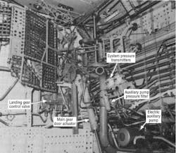
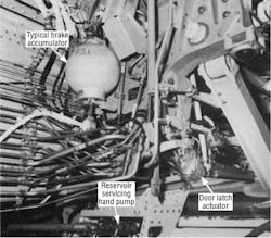
Two control and isolation valves are identical, as are the four actuating cylinders; there are no Left and Right parts. Power for the main wheel brake is supplied by both hydraulic systems. Each brake has two separate sets of power pistons and passageways; each can operate separately. Adequate braking is provided by each of the two hydraulic systems to stop the aircraft in the event of one hydraulic system failure. In addition, braking accumulators provide adequate braking capacity to stop the aircraft in the event of hydraulic system failure, Figure 4.
The tricycle gear extend/retract system consists of two dual main gears and one steerable dual nose gear. The gear and gear doors are normally retracted and extended hydraulically. In the event of loss of hydraulic power, an emergency handle in the cockpit allows the pilot to unlatch the gear manually and operate a dump valve. This lets the gear free-fall and lock in the down position with the help of gravity, air loads, and spring-loaded bungee links.
Dashpots and restrictors control the actuation rate and soften the end positions: the main wheels brake automatically during the initial phase of gear retraction; the nose wheels brake automatically during the last phase of gear retraction.
Each main gear uses identical detail parts, the only difference between left and right gear being in assembly positioning.
The nose wheel steering system is identical to that in the DC-9s. It consists of two cylinders trunnion-mounted to the top of the nose gear shock strut. Each cylinder receives pressurized fluid from a separate hydraulic system and is controlled by its own steering valve. Each cylinder can steer the aircraft in the event of a hydraulic system failure. Each of the hydraulic steering components for the two systems is identical and is interchangeable from right to left hand.
The rudder is powered from the Right system only. However, for redundance, it has tab control reversion, and is common with all DC-9 models.
The system incorporates a manually-controlled shutoff-and-bypass valve, controlled by pilot action. This valve also will automatically shut off if system pressure drops below a predetermined level, thereby reverting the rudder to manual tab control, to insure uninterrupted rudder operation.
The leading edge slat system differs from the DC-9 models: the MD-80 uses a single drive station to operate both wing slats; prior models had individual drive systems for each wing.
Both Left and Right hydraulic systems provide power: pressurized flow from both systems flows into one DC-10 tandem control valve. System isolation is maintained in the control valve, and each system provides power to a left or right slat actuating cylinder, respectively.
The ground spoiler system is new for the MD-80 and consists of one panel in each wing inboard segment. One tandem cylinder operates each panel, and each cylinder is sized so that either hydraulic system can provide enough power in case of a hydraulic failure.
The control valve requires a mechanical input and an electrical input to open. If the two signals do not agree, the valve remains in the stow mode. When both valve signals command deploy, the panels are driven to the full deploy position. The drive linkage provides an overcenter lock in the stowed position to prevent float in the unlikely case both hydraulic systems should fail.
The ventral stair is a standard feature on all MD-80 aircraft to provide a rear exit, in addition to the forward exit. The stairway is actuated hydraulically by a simple cylinder and manual control valve which receives power from the Right hydraulic system. The stair can be unlatched manually and extended by gravity in case hydraulic power is not available. Its control valve is spring-loaded to the neutral position to provide system isolation when the stair is not in use.
The author, Robert T. Madison, was unit chief—design, DC-9/MD-80 Hydromechanical Systems, Mechanical Engineering Subdivision, Douglas Aircraft Co., McDonnell Douglas Corp., Long Beach, Calif., when this article was originally published in Hydraulics & Pneumatics.
This file type includes high resolution graphics and schematics when applicable.
About the Author

Leaders relevant to this article:
